
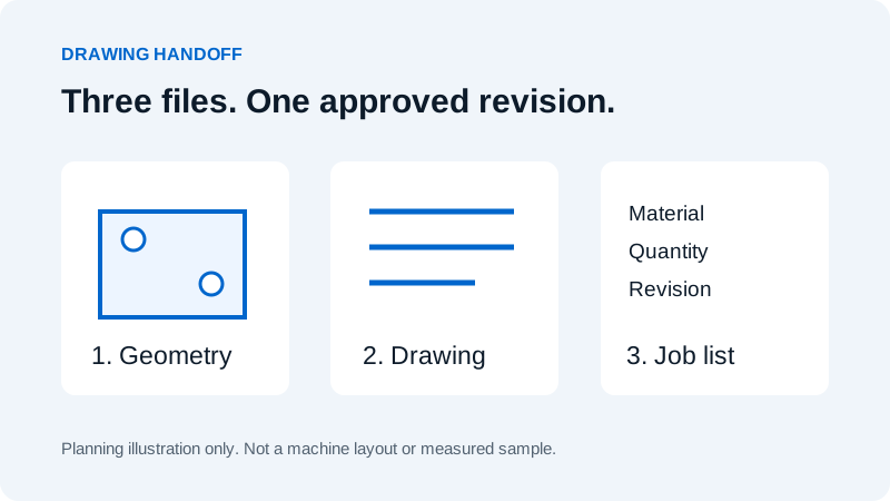
Send geometry at the intended scale, a matching dimensioned reference drawing, and a job list identifying material, thickness, quantity and revision. Confirm the file type and export version with the team programming the specific machine.
Build a drawing pack, not just a geometry file
A DXF can describe the shape of a flat part, but the file alone may not tell the programmer which material to cut or which dimensions matter most. A useful laser cutting handoff combines geometry with a readable reference drawing and a short job list. The three should describe the same approved revision.
For sheet parts, ask the programming team whether it wants individual flat profiles or a prepared nest. For tube or profile work, confirm the required model and supporting drawing. A STEP file can carry three-dimensional geometry, but accepting that file does not automatically establish a production-ready tube program.
Agree on the accepted format, version and any export settings before sending a large batch. BOCHU's CypCut workflow overview separates drawing import from optimization, technique setup, toolpath planning and machining checks. Import is one stage of preparation, not the whole process.
Check the exported geometry
- Confirm units and scale. State millimetres or inches in the job list and compare one known overall dimension after import. Do not rely only on how large the part looks on screen.
- Check contours. Inspect intended closed boundaries for gaps, crossings and duplicate entities. Identify intentionally open marks separately from cut profiles.
- Separate reference information. Keep dimensions, title blocks, construction lines and notes out of the production geometry unless the programmer explicitly requests them.
- Identify operations. Explain which features are to be cut, marked or omitted. Agree on layer mapping; a colour is not a universal machine instruction.
- Reopen the exported file. Check holes, arcs and small features against the reference drawing. An apparently successful export can still need correction.
Do not simplify curves using an arbitrary tolerance. Ask the programmer which geometry types the installed software supports and how the export will be checked. A change that makes a file easier to import must not silently change the intended part.
Use a file handoff checklist
| Deliverable | Include | Check before sending |
|---|---|---|
| Geometry file | Part number and revision in the filename | Units, overall size, complete profiles and operation mapping |
| Reference drawing | Dimensions, tolerances and relevant notes | The drawing revision matches the geometry |
| Material list | Grade, thickness or tube section, and quantity | No material is inferred from a filename alone |
| Process requirements | Finish, grain direction, marking and next operation | Restrictions on rotating or mirroring parts are explicit |
| Change record | What changed and which files are superseded | Only one current production revision is identified |
Use consistent names such as BRACKET-042_REV-C.dxf and BRACKET-042_REV-C.pdf. That is an example naming convention, not a required Wavlon software format. Keep obsolete versions out of the active delivery folder and retain them in your own revision history.
Separate sheet and tube requirements
For bent sheet parts, identify whether the supplied profile is an approved flat pattern. The intended bend process and allowances must be agreed; the laser programmer should not have to infer a developed shape from an assembly image. State any grain-direction or cosmetic-face constraint before nesting.
For tube parts, include section dimensions, wall thickness, material, finished length, relevant joint geometry and orientation requirements. Distinguish a finished-part model from the available raw stock. Ask the supplier to review machine access, support and unloading alongside geometry.
Leave kerf compensation, lead-ins and cutting sequence to the agreed CAD/CAM workflow unless the programming team asks otherwise. Applying compensation in two places can change the result. Document who owns each preparation step.
Confirm the import before the cutting trial
Ask for a preview or written confirmation of the imported part dimensions and intended operations. Resolve missing geometry or ambiguous notes before scheduling the cut. A picture of a part is useful for discussion but is not a substitute for a dimensioned acceptance requirement.
For a repeat job, retain the accepted drawing pack and record later changes explicitly. If the export method changes, check it on a known part before applying it to the whole library. Software changes should follow the machine supplier's compatibility process.
Next, use the sample inspection checklist to decide how the cut will be assessed. For software options, see Wavlon's control systems. Contact Wavlon to confirm the appropriate file handoff for your application.
Frequently asked questions
Should I send DXF or STEP for laser cutting?
Confirm the programming workflow. A two-dimensional profile may be appropriate for sheet work, while tube or three-dimensional work may require a model and supporting drawing. File support depends on the installed software and configuration.
Should I add kerf compensation to the drawing?
Agree this with the programming team. Supply the intended part geometry unless requested otherwise, and document where compensation will be applied so it is not applied twice.